FIRONN - Finite Impulse Response Optical Neural Network.
This work was developed between 1998 and 2000 under a
MURI
sponsored by the Office of the Secretary of Defense (DDR & E) managed
by Dr. William Miceli of the Office of Naval Research.
Pictures of the experimental setup.
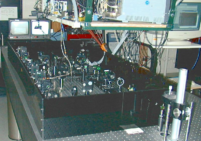
Experimental setup: overall view showing optical table, computer interface
and RF section.
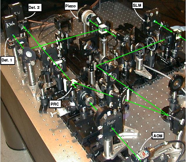
Detailed view, showing main components and beam path. SLM - spatial
light modulator. Piezo - piezo actuated mirror, used in active heterodyne
stabilization. Det. 1 & 2 - detectors used in differential heterodyne
detection. PRC - photorefractive crystal, used for dynamic holographic interconnetcs.
AOM - acousto-optic modulator.
MPEG videos
 Optical setup
, with a close view of the AO modulators, spatial light modulator and photorefractive
crystal. Time-multiplexing is used for holographic recording. Hence, light
diffracted by the AOs is on during recording and off during
readout.
Far-field chirp beamforming
. This video first shows the image of the scrolling SLM with the broadband
chirp to be detected. Then the same image is shown in the Fourier plane,
showing a long and narrow stripe, evidence of a broadband signal in the far-field.
Next, the crystal face is imaged during the read/write process, at a reduced
speed (3.33ms per frame). A straight line slowly appears as an adaptive
grating is formed, resulting from the correlation between the desired signal
and the input image.
Near-field chirp beamforming in the presence of a CW,
far-field, jammer
. This video first shows the image of the scrolling SLM with the near-field
chirp to be detected superimposed by a far-field, CW jammer. Initially the
image scrolls slowly, then at full rate (0.67ms per frame). Then the same
image is shown in the Fourier plane, showing a long and spread-out region,
corresponding to the near-field chirp, which is broadband in space and time.
The jammer is noticed as a very bright spot is seen at the same frequency
of the chirp's center frequency. Next, the crystal face is imaged during
the read/write process, at a reduced speed (3.33ms per frame). A straight
line slowly appears as an adaptive grating is formed, resulting from the
correlation between the desired signal and the input image.
Near-field chirp beamforming in the presence of a CW,
far-field, jammer
. This video first shows the image of the scrolling SLM with the near-field
chirp to be detected superimposed by a far-field, CW jammer. Initially the
image scrolls slowly, then at full rate (0.67ms per frame). Then the same
image is shown in the Fourier plane, showing a long and spread-out wedged
region, corresponding to the near-field chirp, which is broadband in space
and time. The jammer is noticed as a very bright spot is seen at the same
frequency of the chirp's center frequency. Next, the crystal face is imaged
during the read/write process, at a reduced speed (3.33ms per frame). A
curved line slowly appears as an adaptive grating is formed, resulting from
the correlation between the desired signal and the near-field chirp present
in the input image.
Near-field AND far-field chirp beamforming
. In this example, two chirps are detected, one in the near-field and the
second in the far-field. First the image of the scrolling SLM with the chirps
superimposed is shown. Initially the image scrolls slowly, then at full rate
(0.67ms per frame). Then the same image is shown in the Fourier plane, showing
a long and spread-out wedged region, corresponding to the near-field chirp,
which is broadband in space and time. Next, the crystal face is imaged during
the read/write process, at a reduced speed (3.33ms per frame). A straight
and a curved line slowly appear as an adaptive grating is formed, resulting
from the correlation between the desired signal and the two chirps present
in the input image.
Near-field beamforming in the presence of two broadband
jammers
. In this example, a near-field chirp is to be detected in the presence of
a broadband jammer in the far-field AND another broadband jammer in the near-field.
The two jammers occupy the same frequency region of the chirp, but are located
at different spatial positions. First the image of the scrolling SLM with
all 3 signals superimposed is shown. Initially the image scrolls slowly,
then at full rate (0.67ms per frame). Then the same image is shown in the
Fourier plane, showing a long and spread-out wedged region close to the center,
corresponding to the near-field chirp. To the right of the chirp there is
another wedged region, corresponding to the near-field jammer. To the right
there is a sharp line, corresponding to the second, far-field broadband jammer.
Next, the crystal face is imaged during the read/write process, at a reduced
speed (3.33ms per frame). A parabolic line slowly appear as an adaptive
grating is formed, resulting from the correlation between the desired signal
and the desired near-field chirp present in the input image.
I would like to thank Eric Hoyt for the help extended
in the digital capture of the videos shown above.
Relevant publications (PDF format):
-
Paulo E. X. Silveira, G. S. Pati and Kelvin H. Wagner, ``
Optical Implementation of a Single-layer Finite Impulse Response Neural Network
'', Int. Conf. on Optics in Computing, 2000.
-
Paulo E. X. Silveira and Kelvin H. Wagner, ``
Optical Finite Impulse Response Neural Networks.
'', Proceedings of the SPIE, vol. 3804, 1999.
-
Paulo E. X. Silveira and Kelvin H. Wagner, ``
Optical Architecture for Finite Impulse Response Neural Networks.
'', International Conference on Optics in Computing, 1999.
-
Paulo E. X. Silveira and Kelvin H. Wagner, ``
Time Delay Optical Neural Network.
'', International Conference on Optics in Computing, vol. 34, no.
90, pp. 266-269, 1998.
-
 Back to my home page.
Last Modified: 24/Mar/2002
Paulo E. Silveira /
pauloexs@gmail.com